In today’s post, I want to dive into an idea I haven’t been able to shake: integrating deep UV laser lines into a flow cytometer. This isn’t just about adding another laser—it’s about fundamentally rethinking how we collect and process fluorescence data.
The Challenge: Reaching Beyond 50 Colours
Flow cytometry has come a long way. Traditional cytometers allowed us to measure up to 28 parameters, and full spectral cytometry has pushed that to around 50. But compared to the 3000+ parameters of single-cell RNA-seq, we’re still scratching the surface.
We’ve optimised the standard laser lines—355 nm, 405 nm, 488 nm, 561 nm, 633 nm—by squeezing in as many dyes as possible per line. The next logical step is to add new excitation sources. But introducing a new laser line isn’t easy.
When Sony introduced a 320 nm laser in the ID7000, it came with no commercial dyes. This is partly a business decision—companies that sell both reagents and instruments don’t want to give competitors an edge. Scientifically, though, the 320 nm line has merit. It’s excellent at exciting cellular autofluorescence, which I believe is a strength, not a weakness. More on that in a later post.
In 2024, William Telford published a paper demonstrating a 266 nm laser retrofitted into a BD LSR II. It worked beautifully—exciting Qdots well but bypassing most of the Brilliant UV (BUV) dyes. This makes 266 nm a unique addition with minimal spectral overlap. The laser from CryLaS was also remarkably stable, a crucial point considering the reliability issues that plagued the 305 nm line from BD.
Defining the Ideal Flow Cytometer
Let’s define what I want in a next-generation cytometer:
- Detection of at least 60 fluorescent parameters—ideally closer to 70.
- Modular design for laser and detector expansion.
- Fluorescence detection from 266 nm to 900 nm.
- Fibre-optic signal collection for alignment simplicity and system modularity.
- Matched detector window size to spectral region (red light = broader windows).
- High sensitivity to low-intensity signals, ideally down to the single-photon level.
- High linearity and dynamic range.
- Fast event processing: ≥50,000 events per second.
- Real-time data streaming and storage.
- Minimal stray light and noise.
- Long-term stability—hours of continuous acquisition without drift.
That’s a long list. Let’s walk through how to deliver on it, starting with the UV path.
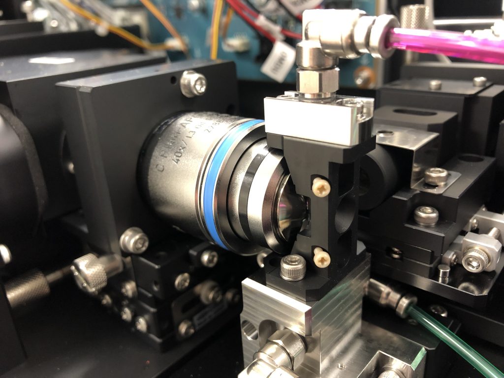
UV Excitation Optics and Flow Cell Design
Deep UV light at 266 nm can’t pass through standard optical materials. We need mirror-based alignment to direct the beam into the flow cell. Typically, this can be achieved with three dielectric-coated, UV-enhanced aluminium mirrors. The key here is keeping the 266nm laser close to the flow cell.
The flow cell must be constructed from high-grade fused quartz, which remains transparent at 266 nm. Most commercial flow cells already use quartz, but surrounding components—especially plastic housings—will need to be replaced with UV-resistant materials such as PEEK or anodised aluminium to prevent degradation.
Light Collection and Fibre Coupling
Efficient signal collection starts with high-NA optics. The emission cone from the interrogation point must be tightly focused into a UV-grade multimode fibre. However, deep UV light degrades fibre coatings and suffers from high attenuation below 300 nm (only ~30% transmission at 300 nm).
To prevent fibre damage and extend system lifespan, I incorporate a 320 nm long-pass filter at the interface between collection optics and fibre. This blocks harmful DUV photons while passing most of the biologically relevant fluorescence.
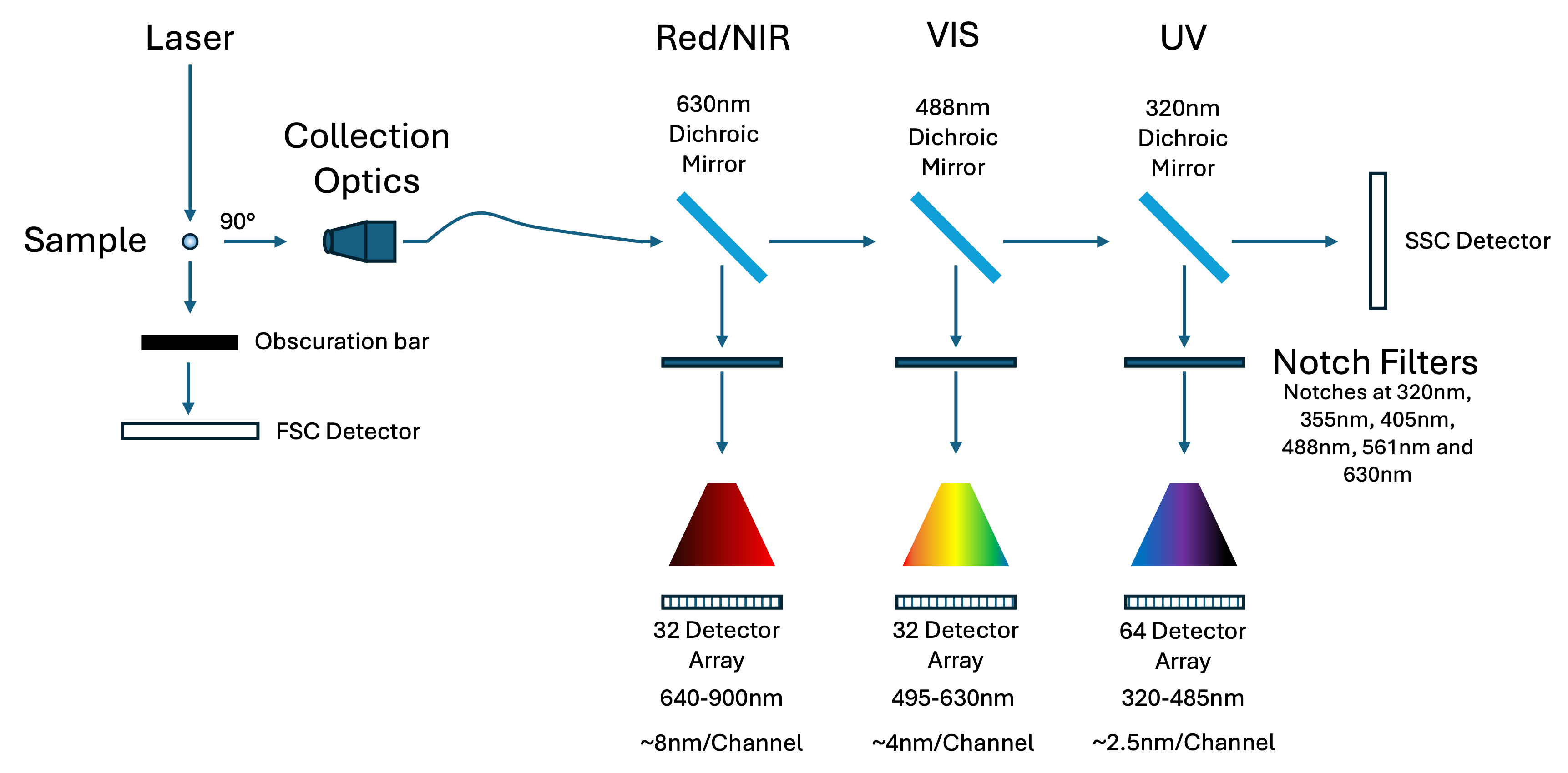
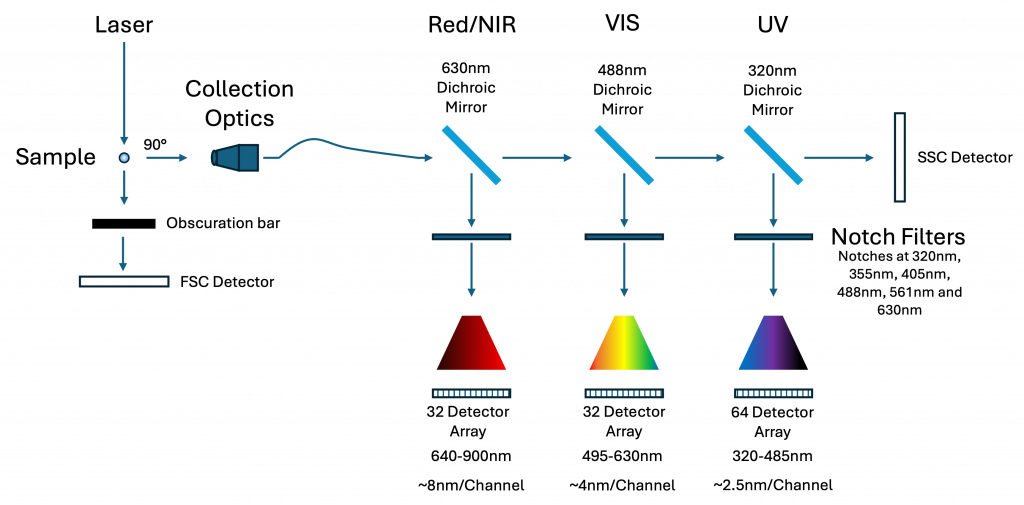
Splitting the Spectrum: Three Detector Modules
Because no single diffraction grating can efficiently cover 320–900 nm, I divide the spectral signal into three discrete modules:
- UV module: 320–485 nm (64 detectors)
- Visible module: 485–640 nm (32 detectors)
- Red/NIR module: 640–900 nm (32 detectors)
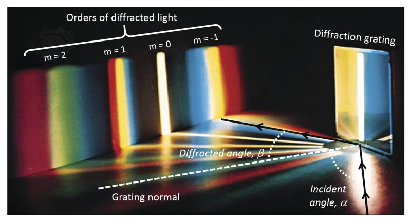
Each module uses a transmission diffraction grating optimised for its band. The gratings are mounted at different incidence angles to favour first-order diffraction:
- UV detector: 0° (collecting either +1 or -1 order)
- Visible: ~10.6°
- NIR: ~48.5°
This design not only respects the physics of diffraction but also aligns detector resolution with spectral complexity: more channels are assigned to regions with denser emission spectra.
Optical Stray Light Suppression
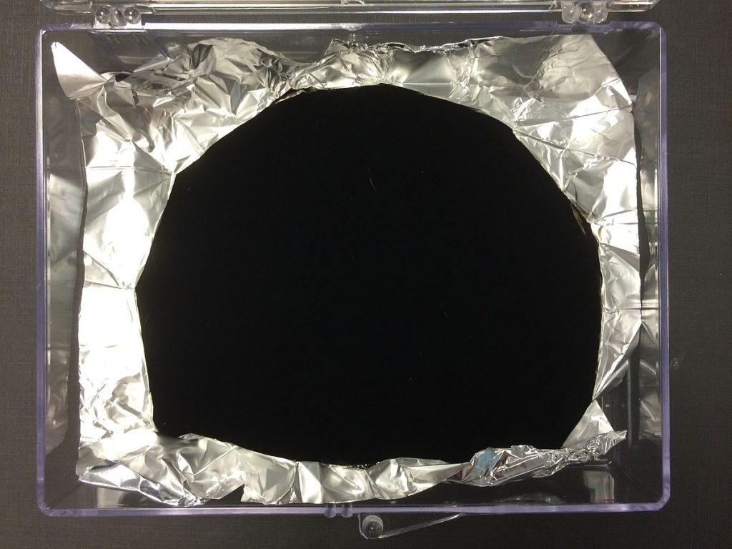
To maximise signal fidelity, stray light must be suppressed at all stages. Inside each detector module, all interior surfaces are coated with Vantablack, which can absorb 99.999% of all light. This drastically reduces internal reflections that could otherwise lead to spectral contamination.
Light baffles are used between optical components to prevent zero-order or scattered light from reaching the detectors. Each module is fully enclosed in a light-tight housing, ensuring only first-order diffracted light reaches the sensor.
Detector Selection and Cooling
Each spectral module uses either a 32- or 64-channel linear silicon photomultiplier (SiPM) array, such as the Hamamatsu S13552. These arrays offer:
- High photon detection efficiency (PDE) from ~320–900 nm
- Single-photon sensitivity
- Fast pulse rise times (sub-microsecond)
- Low operating voltage (~50 V)
To reduce thermal noise and dark count rates, each array is cooled to 0°C using a Peltier thermoelectric cooler. This is crucial: SiPM dark counts roughly halve for every 10°C drop in temperature.
But cooling introduces another challenge—condensation.
Sealed Detector Chamber and Dry Nitrogen Atmosphere
To prevent condensation on cold detector surfaces, the entire detector and optics assembly is enclosed in a sealed aluminium housing filled with dry nitrogen gas. This not only prevents fogging but also protects sensitive electronics and optical surfaces from humidity-induced damage.
A nitrogen purge valve allows easy flushing of the chamber prior to operation. Inside, a small desiccant pack serves as a backup moisture trap. The chamber includes a PTFE vent membrane to equalise pressure without allowing ambient air or water vapour in.
This setup ensures consistent, long-term operation—even during multi-hour acquisition runs.
System Modularity and Detector Allocation
Each laser line is mapped to a corresponding detector set. The modular architecture allows detector modules to be removed or added depending on the laser configuration.
Here’s the proposed allocation:
- 266 nm – 128 detectors
- 320 nm – 128 detectors
- 355 nm – 114 detectors
- 405 nm – 95 detectors
- 488 nm – 64 detectors
- 561 nm – 48 detectors
- 633 nm – 32 detectors
- SSC/FSC – 7 detectors
Total: 616 channels.
By any metric, that’s an enormous amount of data generation—and that brings us to processing.
Signal Amplification and Digitisation
Each SiPM channel produces a fast, low-level current pulse. These are converted to voltage using transimpedance amplifiers (TIAs) placed directly adjacent to the detectors. This minimises trace length and noise pickup.
To further protect signal integrity:
- Active RF shielding is used for all analogue traces.
- The entire amplifier section is cooled with a shared heatsink and thermoelectric cooling.
- Power rails are filtered and isolated to avoid noise coupling from digital circuits.
Each signal is digitised using 14-bit ADCs running at ~10–20 MS/s per channel. These feed into a high-speed FPGA, which extracts area, width, and height parameters per pulse.
Real-Time Processing and Storage Architecture
At 50,000 events per second across 616 detectors, we’re generating up to 0.6 GB of data per second. To manage this:
- Each laser line has a dedicated GPU for real-time processing and spectral unmixing.
- Data is first written to a PCIe SSD RAID array (RAID 0 or RAID 5) for speed.
- Long-term storage is handled by a larger HDD RAID system.
To reduce storage load, baseline subtraction and digital thresholding are applied on the fly, and only valid fluorescence events are saved.
Conclusion: Why This Matters
This design brings us closer to a truly high-dimensional, modular spectral flow cytometer. I have added a 266nm laser line increasing the possible number of dyes by roughly 12. I have also increased the NIR range to 900nm adding a possible total of 7 dyes. The higher number of detectors will also increase the number of dyes that can be used together but it is harder to guess by how many. As a rough ball-park number I would think this cytometer design could separate 75-colours.
The best thing about this design is that there are no new inventions here, every item is commercially available or a minor modification to an existing commercially available item. There are no new ideas here either; every adaptation is taken from existing cytometers, spectrometers or microscopes. Given a sufficient budget this design could be set up on an optical breadboard within 6 months to a year. A commercial device could be in place within two years.
Of course, a commercial device like this would cost in the region of $1 million USD (Around 50% more than a current high-end cytometer). It is a lot of money but not outside the norm for high-end scientific equipment.
In my next post, I’ll explore how the 266 nm and 320 nm laser lines can be used not just to increase dimensionality, but to unlock autofluorescence as a functional readout—potentially revealing new cellular phenotypes we’ve never seen before.
Leave a Reply